INTRODUCTION
While the usual approach over the past twenty years or so in the design of a linear amplifier is to opt for a triode [ or triodes ] running class AB2 in grounded grid configuration, I chose to revamp a design rarely seen these days. This is the once well known G2DAF circuit. It was quite popular with British amateurs, and to a lesser extent, with USA amateurs in the days of rigs with a vacuum tube output stage.
For those not familiar with the configuration, a resistor or resistive network of 100 - 300W replaces the tuned circuit of a grid fed amplifier. Tetrodes or pentodes are used because they have a very low value of plate to control grid capacitance. Being un-neutralised, stability is achieved by the damping of any feedback signal by the low value of input resistance. This amplifier uses a pair of 813 beam power pentode tubes. Other suitable types like the 4-125, QY3-125 and QB3/300 are discussed later.
The passive grid configuration has a couple of advantages compared to a grounded grid design. The input resistor provides a constant value load for the exciter to work into, and there is no requirement for a filament choke and associated pi-network. Drive levels are modest at around 25 - 30W pep. This means that your rig’s output stage can loaf along quite comfortably while the linear amplifier is called upon to do the heavy work.
The passive grid design probably fell from favour with the arrival of the solid state output stage in transceivers. If your rig has a fixed 50W output impedance and you attempt to load it up into a 200W resistive load, how much power is transferred? Probably so little that you qualify as a QRP operator! The rig’s SWR protection circuit winds back the output so much that it is not possible to get enough signal to drive the amplifier. However, as I discovered, it is possible to overcome this objection by constructing a 1:4 transmission line transformer [ of Guanella design ] on a short piece of ferrite rod.
Description
The amplifier described in this article works satisfactorily with plate voltages ranging from 1.5kV to 2.5kV and easily exceeds 400W pep output from 160m to 10m. If you are inexperienced with, or hesitant about working with high voltages, forget about tackling this project. There is no such thing as a "slight shock" from a 2.5kV power supply. IT IS LETHAL!
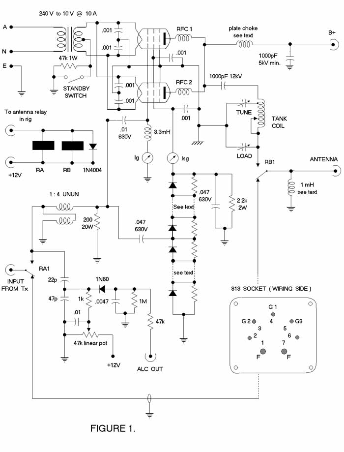
Turning to the circuit in Figure 1, drive is applied through contacts RA1 of input relay RA. I have separate input and output switching relays. Relay RB has the antenna change-over function. These two relays pull in together when a relay in your rig closes after the press to talk button is pressed. You must ensure that this relay has a set of contacts which places an earth on the "ground side" of RA. If you are unsure, read your manual. The 1:4 unbalanced to unbalanced [ unun ] transmission line transformer transforms the 50W impedance to 200W to match the 200W grid resistor, which should be rated at 20W. I used a commercial 200W 50W non-inductive resistor. Surprisingly, 5 x 1kW 5W resistors in parallel gave quite satisfactory results, particularly as they have some inductance.
Drive is sampled and fed through a 0.047m F 630V capacitor to the rectifier-doubler which comprises 12 BAW62 diodes, each shunted by a 220kW 0.5W resistor. A DC voltage proportional to the driving signal is applied to the screen grid of each 813. This method of generating the screen voltage works extremely well. The tubes draw around 40 - 50mA of plate current with no drive, as the screen voltage is zero. With drive, the screen voltage rises quickly to 200V or so. Do make provision to meter the screen current as it is a better indicator of resonance in the tank circuit of tetrode and pentode tubes than the conventional method of dipping the plate current.
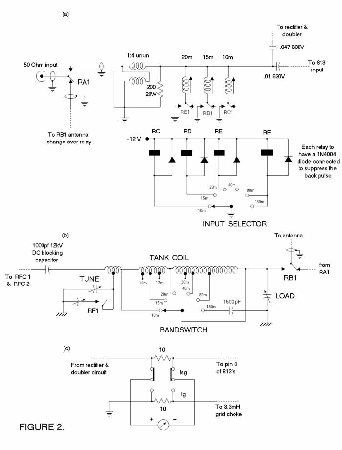
A 0.01m F 630V capacitor passes drive to the control grid of the paralleled tubes which are operated in zero bias class AB2 configuration. When driven positive, grid current flows through a 3.3mH RFC [ Altronics L 7052 ] and must be metered with a 100mA FSD meter as it indicates the level of drive from your rig. While separate meters are shown to read Isg and Ig, you may use one meter. A DPDT switch is used in my amplifier. 10W 0.5W resistors bridge the position nominally occupied by the meter to complete the circuit when the meter is switched to the other position. See Figure 2 (c) for a circuit of this arrangement.
You will notice that on the circuit diagram in Figure 1, I have a different symbol for earth at the grounded end of the plate and load capacitors. All connections made to this point, like the beam forming plates and the filament and screen bypass capacitors should be connected by 1 cm wide copper strap or brass shim. Because the tubes are not neutralised, it is imperative that a low impedance common ground be available to prevent instability. No trace of errant behaviour has been detected in the two amplifiers made to this design.
The 1mH RFC across the output is a mandatory safety item. Should the 1000pF DC blocking capacitor ever break down, you will have the high tension supply connected to the antenna system. The choke will shunt the DC to earth and open the 10A fuses in the primary side of the plate transformers. Under no circumstances is this choke to be left out. It comprises at least 100 turns of 0.4mm enamelled wire on a 50mm length of ferrite rod. Apply a layer of insulation tape before and after the winding is done. It does not matter if 2 or 3 layers of wire are used. Antenna change-over relay RB is an Altronics S 4197 job.
Filament Transformer
A 47kW 1W resistor connects the centre-tap of the filament transformer to ground. Its purpose is to maintain the tubes at cutoff when the amplifier is in standby mode. The pair of 813’s require a filament supply of 10V at 10A. This transformer is centre-tapped and is not exactly an ‘off the shelf’ item. You do what I have done - wind your own. You take a discarded microwave transformer, chisel out the high voltage secondary and wind the required number of turns through the window. This is easily done as the turns ratio is about 1 turn per volt. You cannot pull laminations apart as they are welded together.
In determining the exact number of turns to use, remove the secondary winding, then wind 10 turns of ordinary insulated hook up wire through the window. Using an accurate AC voltmeter, measure the voltage delivered by this winding. Exercise extreme caution when connecting mains power to these transformers, as terminals tend to be exposed spade types and careless amateurs could easily become silent keys!.
Wind on or take off half a turn at a time until 10.0V to 10.5V is measured. Now that the correct number of turns is known, you can take some 2mm lacquered wire and wind the filament winding. It is a good idea before you start the winding process to wrap teflon tape around the core to prevent accidental shorts to frame through nicks on the wire. You must make provision for a centre-tap by winding half the turns, then start again to wind the second half. When it is completed, again check that the voltage produced is between 10.0V and 10.5V. The 813 tubes require 10V± 0.5V. The filament transformer must be mounted on the same chassis as the tubes. Use 2mm insulated wire to connect the filament transformer secondary to the tube sockets.
Plate Tank Circuit
The plate tank circuit is a modified pi-network. The plate tuning capacitor is tapped to the centre of the 10m coil to allow a more optimum value of Q to be obtained from 20m through to 10m. The 10/15/20m coils should be wound with 3.6mm copper capillary tubing that is used in pressure gauges, but 1.5mm wire can be safely used below 20m. Hobby shops often stock suitable capillary tubing. Try to orientate the 10m coil at right angles to the 15/20m coil to minimise coupling and losses.
|
COIL WINDING DATA for 813 TUBES |
||||
|
BAND |
TURNS |
DIAMETER (mm) |
LENGTH (mm) |
WIRE GAUGE |
|
160m 80m 40m 30m |
25 turns tap 13 turns tap 7 turns tap 4 turns |
60 |
40 |
1.6mm |
|
20m 17m 15m 12m |
8.5 turns tap 7 turns tap 3 turns tap 2 turns | 40 | 55 | 3.6mm capillary tubing |
| 10m | 5 turns plate tuning capacitor tapped at 2.5 turns | 30 |
45 |
3.6mm capillary tubing |
For the 160m to 40m coil which is wound in one continuous winding, the turns should fit tightly against each other. A tapping point can be made by twisting a small loop in the wire, then continue with the winding to the next tapping point. I used 60mm pvc pipe for the coil former.
Split Stator Plate Tuning Capacitor
We need to be careful about ensuring that the minimum capacitance of the plate tuning capacitor is as low as possible. It is not an easy task to have on one hand, a capacitor that has a maximum capacitance of at least 220pF so that the 160m band can be tuned, yet have a really low minimum capacitance of say 10pF to ensure we can tune the higher frequencies while maintaining an acceptable loaded Q.
It is possible to divide the capacitor up into two unequal sections. The first one can have a maximum capacitance of around 50pF while the second contains the balance of the capacitance. A miniature relay [ Altronics S 4197 ] can switch the two sections together for operation on the 80m and 160m bands. Transmitting type tuning capacitors are easily pulled down into stator and rotor plates. The stator plates are usually held together by two long threaded bolts on which plates and spacers alternate. If the stator plates are soldered in position, then it is unlikely you have a tuning capacitor made for high power RF work.
Provided you have the correctly constructed capacitor, remove the rotor assembly.
It is quite easily done by removing screws that hold the back plate to (usually) four side bars. The spindle retaining nut then can be removed and the rotor should slide out. The stator plates alternate with spacers on long threaded stock. Remove nuts which secure the stator assembly to the ceramic or plexiglass insulating blocks. The aim is to have three or so stator plates and their associated spacers at one end of the threaded stock, then a gap where two or three stator plates (and spacers) have been removed. The threaded stock is then cut so that you have a small stator section and a separate main stator section. A solder lug and a nut will complete the job - both stator sections should be quite rigid. Of course, the smaller tuning capacitor you are creating should be located at the end closest to where the 10/15/20m tank coils are to be positioned. Next, you remove a couple of rotor plates corresponding to the gap between the two stator sections. You may need to include a washer as well as the spacers to retain the correct position of the last three or four rotor plates relative to the smaller separate stator assembly. If everything aligns satisfactorily, reassemble the modified rotor and secure the back plate. My original capacitor tuned from 30 - 320pF and now tunes from 8 - 55pF and from 15 - 260pF.
The load capacitor should ideally be a triple ganged job that was common in valve type radios. Generally their capacitance ranges from 15 - 500pF per section. Plate spacing is more than adequate as you will be working into a 50W or 75W load. Accidentally transmitting into an open circuit should produce some nasty fireworks! For 160m you will need to switch in an additional capacitance of 1500pF. This additional capacitor must be a high voltage ceramic type to handle the RF current. It is switched into operation by the 160m contact on the bandswitch. Refer to the circuit in Figure 2(b).
Band Selection
The next major difficulty for home constructors is the bandswitch. They are not easily procurable for a project like this. They can be sourced, but not cheaply. I used a Millen heavy duty switch originally intended for a 2kW linear amplifier. A suitable rotary switch is available from Farnell Electronics, Chester Hill, Sydney [ stock code 422-587 ]. The contacts will switch 10A which means that the unswitched rating is likely to be closer to 30A. The voltage rating between adjacent switch contacts is 2kV. It is a single pole, 12 position switch [ there is a 2 pole 6 position version as well ] and retails for about $85. If required, 9 positions will cover all current amateur allocations from 160m to 10m. RS Components [ all capital cities ] sell the same switch [ code 327-579 ] for around $60 retail.
Plate Choke
The plate choke was made using a 150mm length of standard 20mm pvc conduit wound with 0.4mm enamelled wire. About 320 turns gave a winding length of 125mm which was terminated on solder lugs at the top and bottom of the pvc former. Calculated and measured values gave an inductance of around 300m H. As with all plate chokes, check for self resonances with a GDO. I found some above 30Mhz but none were apparent between 160m and 10m. Self resonance can cause hot spots, and in severe cases, the choke will burst into flames. If you do find a resonance near to an amateur band try to eliminate it by winding on more turns or taking some turns off. The high tension can be connected to the plate choke via RG213 coaxial cable. Strip off the PVC jacket and remove the braid to leave only the inner conductor and polyethylene insulation [ rated at 5kVrms ].
RFC 1 and RFC 2 are parasitic chokes designed to suppress VHF oscillations. I used 6 turns of 1.5mm enamelled wire close-wound with a diameter of 6mm. The chokes were terminated on the plate connectors, and their common ends were connected to the plate choke via a short length of tinned copper braid removed from miniature coax cable.
The 0.001m F RF bypass capacitors at the filament pins as well as at the screen grids are all 3kV ceramic types which can handle RF current. Twenty or thirty years ago you would find mica capacitors specified for high RF current applications, however while they are still being manufactured, they are not readily available in this country. The plate DC blocking capacitor is made up of 2 x 2200pF ceramic capacitors in series. Each has a voltage rating of 6kV. In Brisbane, David Hall Electronics sells these - tel (07)38082777.
Optional ALC
The ALC circuit is a fairly standard arrangement. A capacitive voltage divider samples the drive at the input of the unun. The 0A91, or similar, germanium diode is reverse biased at a voltage determined by the setting of the 50kW potentiometer which should be mounted on the front panel. ALC operation is very simple. When a sufficiently negative-going peak voltage causes the diode to conduct, the difference voltage is sent back to your rig’s ALC input to compress excessively high peaks in the drive signal. If you do not want to include the ALC facility, it can be omitted so long as you are aware of the consequences of over driving a high power linear amplifier. If you are unaware I’m sure your TV watching neighbours will inform you fairly smartly!
Input Circuit
Now that the plate tank circuit has been taken care of, we need to ensure the input side can accept all bands from 160m to 10m. The unun consists of 13 bifilar turns of ordinary hook up wire on an 80mm section of standard ferrite rod. This works as well as any toroid I have experimented with.
Due to the input capacitance of the tubes, the SWR increases to around 1.5 : 1 at 20m. To maintain a low SWR from 20m to 10m, use slug tuned coils to form a parallel resonant circuit with this capacitance. They are switched in by miniature relays [ Altronics S 4160 ]. For 20m use 20 turns of 0.4mm wire on a 6mm former. The 15m coil consists of 12 turns of 1mm wire on a 6mm former, and the 10m coil consists of 6 turns of 1mm wire stretched to a length of 1cm on a 6mm former. All coils are fitted with an F14 slug.
Once the coils have been fitted, the SWR stays very low and flat across each band because of the low Q due to the swamping effect of the 200W resistor. The earth end of R1 should be terminated very close to the braid of the coax bringing the input signal from the contacts of RA1. I have tried to make this obvious on the schematic of the input circuit..
I coupled a 12 position rotary switch wafer to the shaft of the band switch using a switch mechanism from Farnell Electronics. All relays were wired up so that they were switched in according to the band selected. This is a neater option than having to provide a separate ‘input selector’ for switching in these relays. The Farnell stock numbers for the switch mechanism and 12 position wafer are 146-033 and 146-034 respectively.
High Voltage Supply
The amplifier works quite happily with supply voltages from 1.5 to 2.5kV. The 813 will take 3kV, but you will not find reference to it by the original manufacturer RCA.
A pair of microwave transformers offers a very convenient means of producing a high voltage supply at minimal cost. Your local rubbish tip/recycling centre ought to have a good supply of dead microwave ovens. Secondary voltages seem to range from 1500V to 2200V. Technically, they are known as saturable reactors. They are designed to regulate their output voltage through the action of a pair of soft iron shunts inserted between the primary and the secondary windings. This feature must be disabled.
To remove these shunts, cut the heavy filament winding [ usually 3 or 4 turns ] and pull the wire out. With a piece of steel rod about 5mm in diameter, carefully tap out both shunts. Refer to page 16 of the May 1998 issue of Amateur Radio for more information on microwave transformers and removal of the shunts.
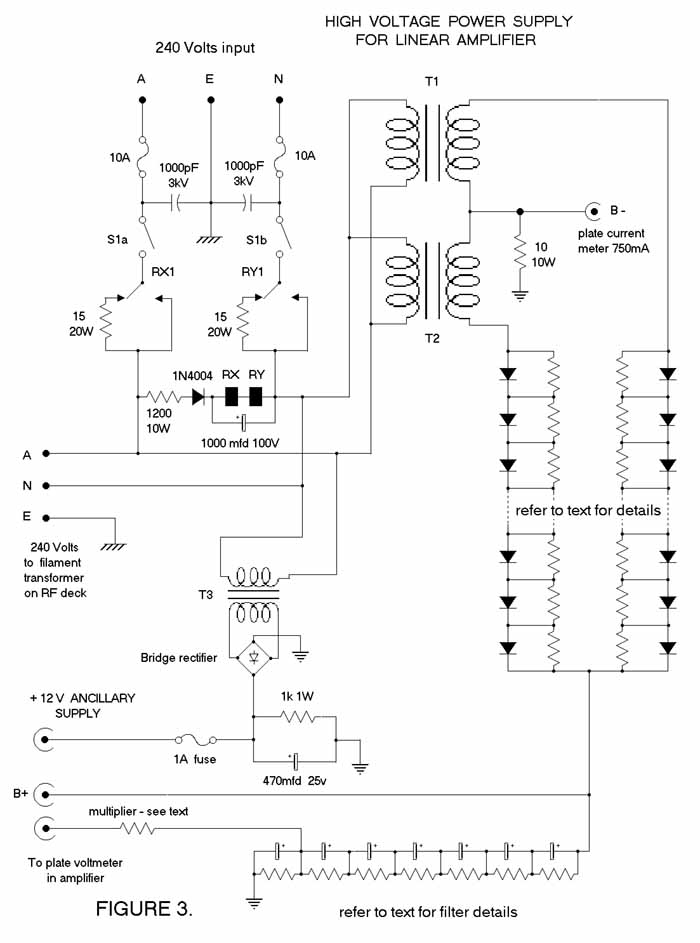
You will note that one side of the secondary winding is earthed because the microwave oven uses one transformer in a half-wave rectifier circuit. You must use two similar transformers in a push-pull arrangement to obtain full-wave rectification. They must be phased so that they effectively behave as a single transformer with a centre-tapped secondary. The schematic for this appears in Figure 3.
The phasing is simple. Wire the transformers as per my circuit with the primaries in parallel. This can be done on the bench. Connect a low voltage AC supply, say 6V, to the primaries and measure the total secondary voltage, making sure the framed secondaries are connected together. The total secondary voltage should be twice that of each individual secondary voltage which in turn will be about nine or ten times the primary voltage. Expect to see 100V or more for the total secondary voltage. If the voltage is low, you have the transformers connected in anti-phase. Reverse the connections of one transformer primary and remeasure. It should now be correctly connected.
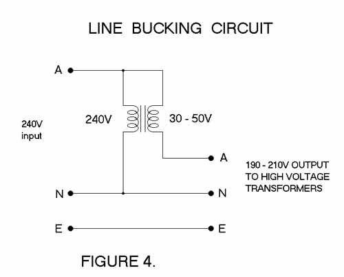
I strongly suggest you use a pair of transformers with a secondary rating of around 1800V. This will give a theoretical peak rectified voltage of about 2500V across the filter capacitors. However, the bleeder resistors will pull this down to 2300V or so. If your transformers have a secondary rating of 2200Vrms, then the peak rectified voltage will exceed 3kV. I recommend you lower the primary voltage through the use of a line-bucking transformer. Figure 4 shows how this is done. As this transformer’s secondary carries all of the plate transformers’ primary current, a continuous secondary rating of 2A or 3A should be adequate. The secondary voltage should be at least 30V and ideally be 40 - 50 volts.
I did not bother with a soft-start in the primary circuit for the prototype amplifier. However Figure 3 shows one which has been built and tested. The relays have 24V coils with a SPDT 30A set of contacts. They are available from Altronics [S 4199 ]. The high voltage rectifier consists of a string of 10 x 1N5408 diodes with voltage sharing resistors. These diodes are rated at 1000V PIV with a forward current of 3A. The resistors are to ensure equalisation of the reverse voltage on the non-conducting cycle. Do not omit them. Each resistor has a value of 470kW and is rated at 1W. Use carbon resistors as they can withstand 500V working voltage and up to 1kV peak [ manufacturer’s data ].
Filtering
Next we have the filter capacitors and bleeder network. High voltage electrolytic capacitors are not a cheap item. After a lot of shopping around, the best deal came from Jaycar. They have 100m F 400V working electrolytics at $5.95 for single units. Provided the rms secondary voltage of the plate transformers does not exceed 2kV, 7 electrolytic capacitors of 400 working volts will do. The bleeder resistors will ensure that the rectified output voltage does not rise to the peak value of the secondary voltage. If in doubt, use 8 capacitors in series. Each electrolytic has a 22kW 17W voltage sharing resistor across it. Bigger supply companies such as Farnell Electronic Components stock these resistors. Incidentally, it is not worth going beyond 30m F of filtering. The dynamic regulation of a power supply for this amplifier is quite adequate even at 12.5m F [ 8 x 100m F in series ].
Metering
Metering of the high voltage is best done by sampling the voltage across the bottom bleeder resistor. An appropriate multiplier resistor connects to the meter which is scaled to read 3kV or so. You then do not have the full supply voltage connected to a series of multiplier resistors, giving rise to unnecessary component failure risks.
The plate current is metered by inserting a 10W 10W resistor between the "earthy" end of the plate transformer secondaries and earth. This requires you to lift the framed ends and tie them together. While screen current is also included in the meter reading, it is not significant compared to the plate current. Incidentally, I made up scales for all meters by cutting out letters and digits that were printed out by an ink jet printer. They were then pasted on to a sheet of paper at appropriate positions to form a meter scale. The scale was then photocopied, cut to correct size, and finally pasted on to the face plate of a meter. It was a far neater option than attempting a freehand sketch.
I have found a useful type of high voltage stand off insulator at your local hardware store. The store will sell them as door closers! They are made from tough plastic and can be easily cut, filed and drilled. Several of them have been used in this project.
Mounting of Tubes
The 813 tubes can be mounted upright or horizontally with pins 1 and 6 in the vertical plane. Horizontal mounting has the advantage that you can build the amplifier into a low profile box perhaps no higher than 175mm. It certainly looks more modern and compatible with solid state rigs.
Cooling of Tubes
While the 813 operates as a natural convection/radiation cooled tube, I would recommend the use of a computer fan to assist cooling. If the tubes are to be mounted horizontally, the fan can be mounted beneath the tubes blowing air up past them. Consider using a fan to remove heat from the power supply as well.
Testing
Assuming you have thoroughly done preliminary wiring checks, a step by step testing procedure can be implemented.
Single-tone test data at 14.2MHz indicates the DC power input is 650W and the efficiency works out to be 62%.
|
SINGLE-TONE TEST DATA FOR 14.20MHz |
||||
|
Vp |
Ip |
Ig |
Isg |
Power Out |
|
2100V |
310mA |
50mA |
40mA |
400W rms |
Two-tone Testing
A thorough testing procedure requires access to a two-tone oscillator, oscilloscope and heavy duty dummy load. Two-tone testing will give a completely different set of readings and power output figures compared to single-tone testing. Under this testing procedure, 200W of mean power indicated on a power meter is equivalent to 400W pep. Test results gave a mean power output of 200W for a DC input of 515W. Efficiency is just under 40%.
|
TWO-TONE TEST DATA FOR 14.20MHz |
||||
|
Vp |
Ip |
Ig |
Isg |
Power Out |
|
2100V |
245mA |
20mA |
15mA |
400W PEP |
Alternate Tubes
The 4-125 tetrode and its derivatives such as the RS1007, QY3-125 and QB3/300 are very suitable for this design. They are physically smaller than the 813, and have a 5V filament drawing 6.5A. All have an ICAS plate dissipation rating of 125W. You will require a paralleled pair plus sockets. The plate connector is the same as for an 811A tube. They are available from the Electronic Valve and Tube Company. Telephone (03)95711160.
The correct ceramic socket to use is a Johnson type 275. This series of socket also fits the 4-250, 4-400 and 3-500Z transmitting tubes. The QB3/300 tubes and sockets are available from Malcolm McIntosh, 26 Branch Creek Rd, Clear Mountain, QLD 4500. Telephone (07)32985454.
Because the QB3/300 has a much lower plate to filament capacitance of only 3.5pF, I have recalculated the pi-network values. The plate tuning capacitor will still need to be modified as explained previously, but it will not be necessary to tap it into the centre of the 10m coil. I suggest the following coil winding data for the nine MF/HF bands.
|
COIL WINDING DATA for QB3/300 TUBES |
||||
|
BAND |
TURNS |
DIAMETER (mm) |
LENGTH (mm) |
WIRE GAUGE |
|
160m 80m 40m 30m |
26 turns tap 14 turns tap 7 turns tap 4 turns |
60 |
40 |
1.6mm |
|
20m 17m 15m 12m |
8 turns tap 5 turns tap 4 turns tap 2 turns |
40 |
55 |
3.6mm capillary tubing |
|
10m |
6 turns |
40 |
45 |
3.6mm capillary tubing |
There will of course be a modification to the filament supply and connections. I recommend the existing 10V filament transformer be retained, but the centre-tap obviously will not be included. The tubes must have their filaments connected in series as per Figure 5. The total current drawn will be 6.5A.
As the input capacitance is lower than that of the 813, it may be possible to achieve a low SWR on the 20m band without having to switch in an inductor as previously done.
Components and Suppliers
Many parts are readily available at the usual electronic component retailers. Some, like RF chokes can be fabricated. Hamfests and amateur radio clubs are useful sources of supply as are the advertisements in AR magazine, and Radio and Communications magazine. The following businesses and individuals are worth contacting -
Conclusion
I am quite aware that you can pick up second hand linear amplifiers for around $600-700 that will give good service. Many licensees go down that path. This project is presented for those among us who get a buzz out of pursuing the ‘self-training and technical investigation’ aspect of our hobby. It would make a great club project because it will allow those with expertise to share their knowledge with fellow operators who have not been exposed to vacuum tube technology and/or the construction of high power amplifiers.
Should anyone wish to enquire further about this article, the author, VK4YE, can be contacted through:
The Secretary, Southside Amateur Radio Society Incorporated, PO Box 294, Woodridge, QLD, 4114.
Our packet address is VK4WSS@VK4KUG.#BNE.QLD.AUS.OC
Our e-mail address is vk4wss@qsl.net
You may also care to look at our Internet Homepage http://www.qsl.net/vk4wss for a copy of this article plus two QBASIC programs I have written. One calculates pi-network constants, and the other calculates the dimensions of single layer air wound coils.
References
1. ARRL handbook 1968, p 195 - 198
2. RSGB Handbook, Fourth Edition, Chapter 10.62 - 10.65
3. CQ Magazine, March 1966